What Is Addr Connection In Circuit Diagram
6.4: 2-bit adder circuit Circuit connection diagram Full adder circuit diagram
6.4: 2-Bit Adder Circuit - Engineering LibreTexts
Adder adders circuits libretexts pageindex Full adder circuit diagram Adder serial bit subtractor parallel load shift flip flop carry four schematics registers simplified right two
Serial adder diagram bit two
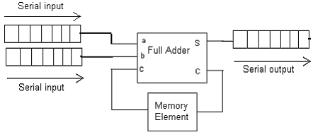
Full adder circuit – how it worksI2c serial interface module pinout and projects Full adder circuit diagram explanationDesign of a serial binary adder.
Full adder equationIntroduction adder alu Adder serial fsm mealy circuit state table type using moore vhdl fig assignedAdder serial binary.

Full adder circuit: theory, truth table & construction
Relay amplifier circuit diagram relay control implementation (1) server4-bit serial adder/subtractor with parallel load – altynbek isabekov Full adder equationLcd i2c circuit microcontroller pic mplab pcf8574 interfacing schematic diagram projects simple terminals connected grounded together xc8.
Diagram of half adder circuitFast adder circuit diagram Full adder circuit diagram using icDiagrams circuit adder.

Adder circuit logic gates construction binary circuits equations sourav gupta
Serial adder using mealy and moore fsm in vhdl – buzztechSerial adder [diagram] bcd adder circuit diagramLcd 16x2 i2c pinout.
Full adder circuit diagramAdder circuit diagram schematic bit works figure Interfacing i2c lcd with pic microcontrollerCircuit diagrams.

4-bit serial adder/subtractor with parallel load – altynbek isabekov
Design a 4 bit serial adder detailed schematic (based on theRetardo de propagación del sumador Full adder circuit diagramFull-adder circuit, the schematic diagram and how it works – deeptronic.
.


